
GX460 seats in an FJ Cruiser, with every wire
Heated and ventilated Lexus seats bolt into the FJ. The wiring is the part nobody writes down. Pinouts, the printed switch connector, the one-pull seat disconnect, and the three things that bit us.
The seats bolt in. The wiring is the whole story.
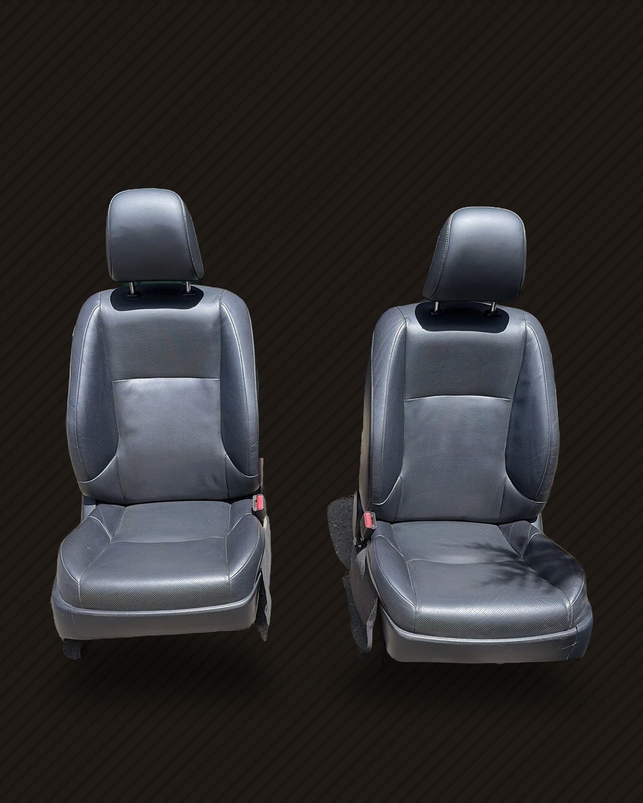
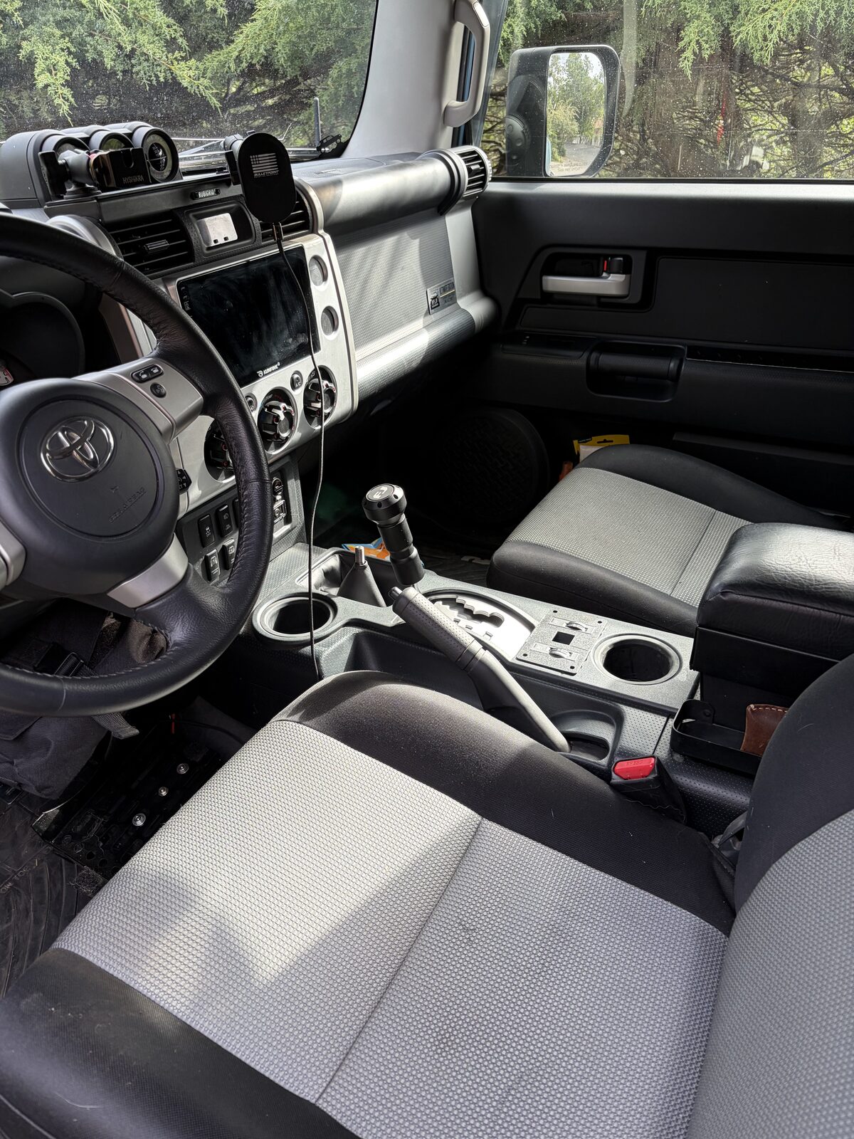
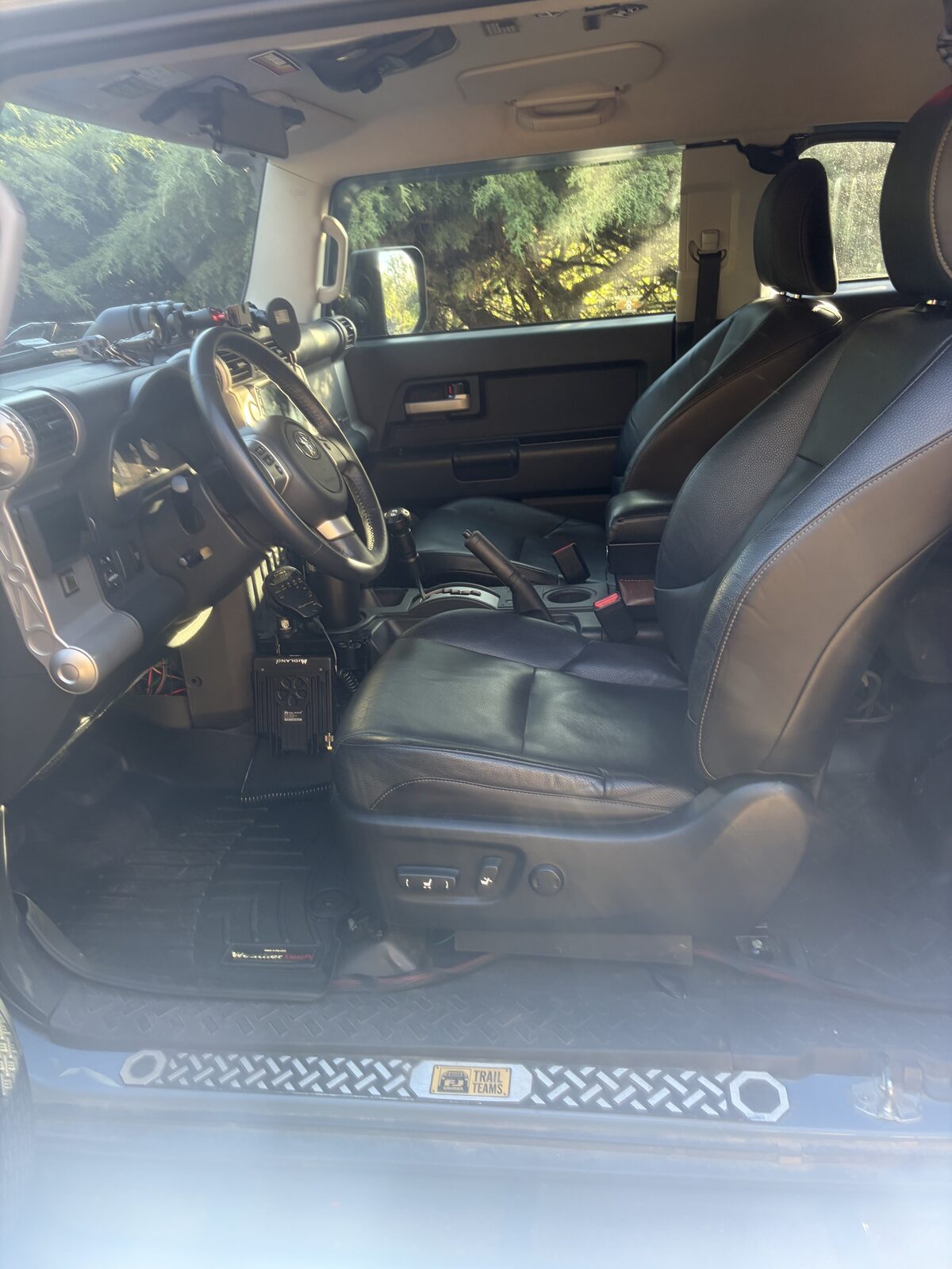
The FJ's front seats are fine until you've sat in something better. Lexus GX460 seats are the same bolt pattern family, they're heated and ventilated, and used pairs show up for a few hundred dollars. Mechanically the swap is an afternoon. Electrically, nobody had written down the whole thing in one place: the switch pinouts, the A/C amplifier the vent function needs, the seat connector pins, and the one pin on the driver seat that leaves the lower motors dead if you miss it. So here it is, verified against the GX460 factory manual and LowVoltage's forum guide, then confirmed on this truck with a meter.
If you're here for the pinouts, skip to the figures. If you're here because your driver seat slides but won't tilt, skip to SYSB.
This is a record of what we did to our own truck, not instructions for yours. We are not engineers, this is not a kit, and nothing here has been reviewed by Toyota, Lexus or anyone who certifies restraint systems. The seats, the airbags, the pretensioners and the occupancy sensor are all part of how the FJ protects you in a crash, and getting any of it wrong can hurt or kill someone. If you do this, you do it at your own risk, you take responsibility for your own wiring and your own airbag work, and you check everything yourself. LRDT accepts no liability for anything you build from this post.
How the seats actually work
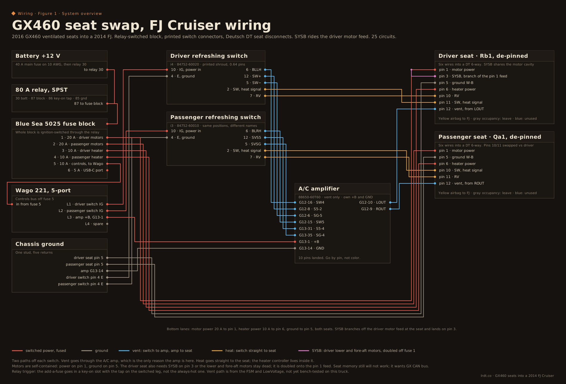
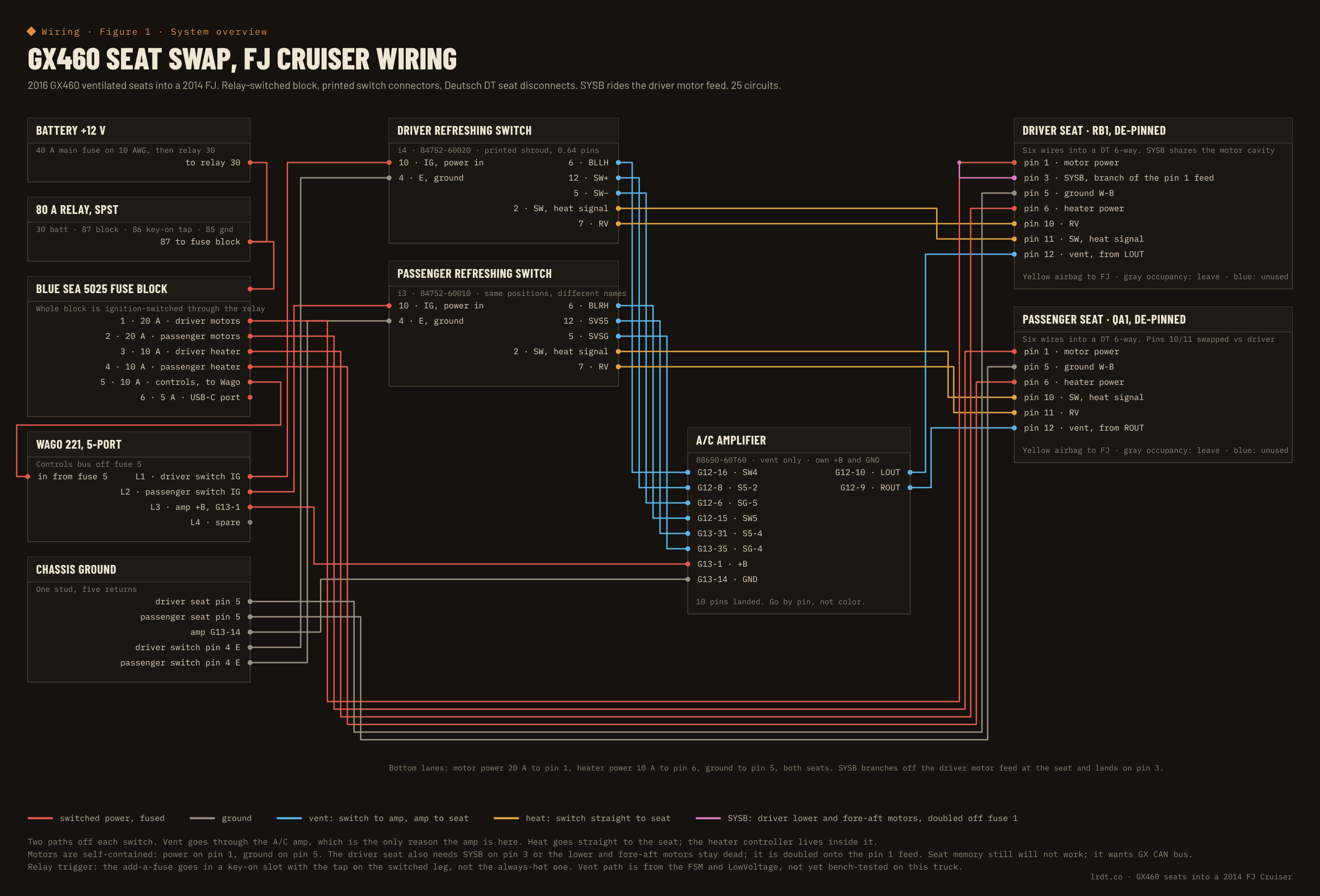
Everything lives inside the seat: motors, heater elements, heater controller, blowers. You never touch the seat's internal harness. You supply power and ground at the seat connector and the seat's own adjuster switch does the rest. The climate side is the part that reaches outside the seat, and it's two separate paths off one refreshing switch.
- Vent goes switch, then A/C amplifier, then the in-seat blowers. The amp turns the switch's resistance into a blower-drive signal. It's the only reason the amp is in this build.
- Heat goes switch straight to the seat. The heater control sub-assembly inside the seat does the work. The amp never sees it.
On the driver seat, connector pin 3 (SYSB) powers the lower and fore-aft motors as well as the position ECU. Leave it off and the seatback reclines but the seat won't slide or tilt. We double SYSB onto the pin 1 motor feed: one 20 A fuse, one cavity in the Deutsch connector, split back to pins 1 and 3 on the seat side. That's safe on one feed because you never run the seatback and the lower motors at the same time. Seat memory still won't work, since it wants the GX CAN bus, but the motors need this pin regardless. The passenger seat has no pin 3; its lower motors are fed through its own connector.
Power: one relay, so the whole thing sleeps
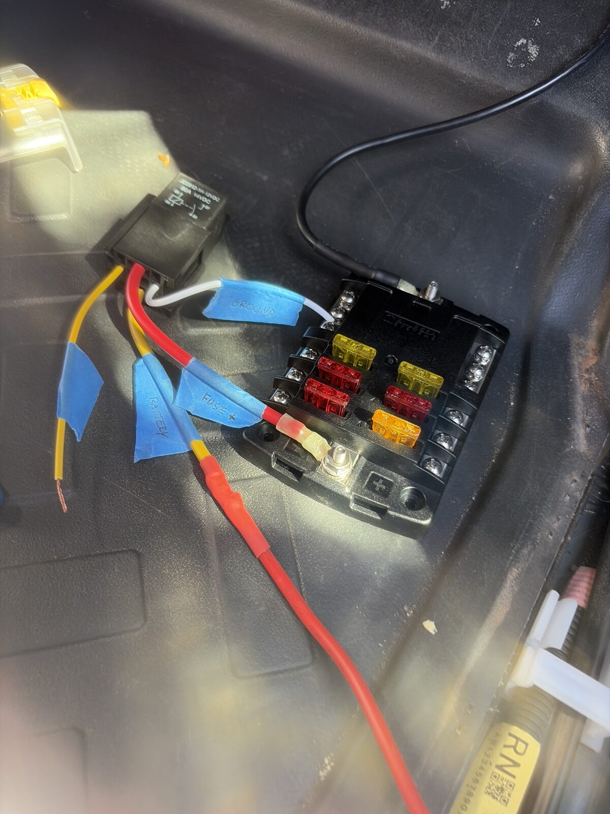
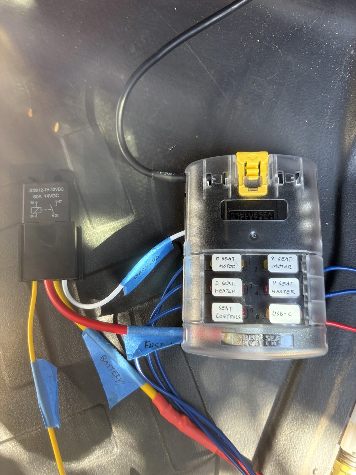
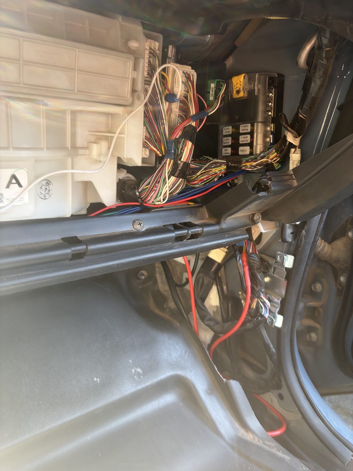
A relay feeds the Blue Sea block's input, so every circuit in the block is ignition-switched from one trigger. Key on, seats live. Key off, seats dead. The relay is an 80 A SPST automotive unit in a socket; 80 is the relay's rating, not a fuse size. The feed from the battery to relay terminal 30 is 10 AWG behind a 40 A fuse, which sits at or below the wire's ampacity and well above real peak draw. The block's own fuses protect the branches, not this run.
| Slot | Fuse | Feeds |
|---|---|---|
| 1 | 20 A | Driver seat pin 1, motor power. SYSB is doubled onto this feed. |
| 2 | 20 A | Passenger seat pin 1, motor power |
| 3 | 10 A | Driver seat pin 6, heater power |
| 4 | 10 A | Passenger seat pin 6, heater power |
| 5 | 10 A | Wago 221 bus: both switches' IG and the amp's +B. One spare port. |
| 6 | 5 A | USB-C port in the switch bezel |
The amp's ground (G13-14) goes to chassis, never through the block. Grounds for both seats, both switches and the amp meet at one stud. On the Wago: strip 11 mm, bare stranded wire with no tinned tips, because tinned ends cold-flow and loosen, and secure the body against vibration.
The relay trigger comes off an add-a-fuse in a key-on slot. Every fuse slot has an always-hot feed contact and a switched output contact, and the add-a-fuse taps one of them depending on which way you insert it. Backwards, you get always-on power from a "key-on" slot, and our seats stayed live with the key off across two different slots before we understood why. Pull the slot fuse, meter both contacts, orient the tap so it draws from the one that reads 0 V key-off and 12 V key-on. Then go audit every other add-a-fuse on the truck, because they're probably not all right either. Ours weren't.
One more thing about key-off on this truck: the solar controller can back-feed the vehicle bus through the dual-battery controller, so in daylight the seats may stay powered with the key off. That's by design; it lets passengers move the seatbacks engine-off without draining anything after dark. It also means that for any airbag work, "key off" is not "power off." Both batteries disconnected and the solar fuse pulled, then wait.
The switch, and the connector Toyota won't sell you
The refreshing switch is the two-button climate control from the GX console. Toyota sells the switch. It does not sell the connector that plugs into it; that only exists pre-installed on the GX console harness. So we made one.
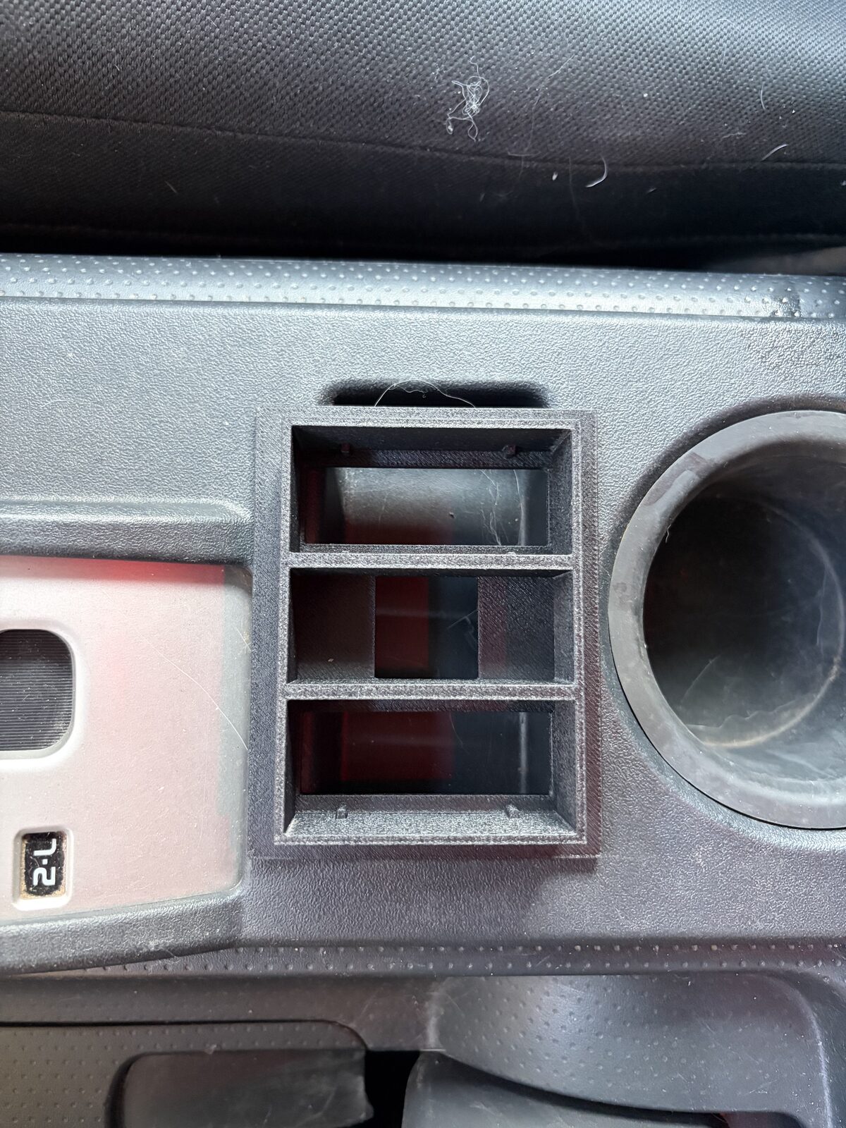
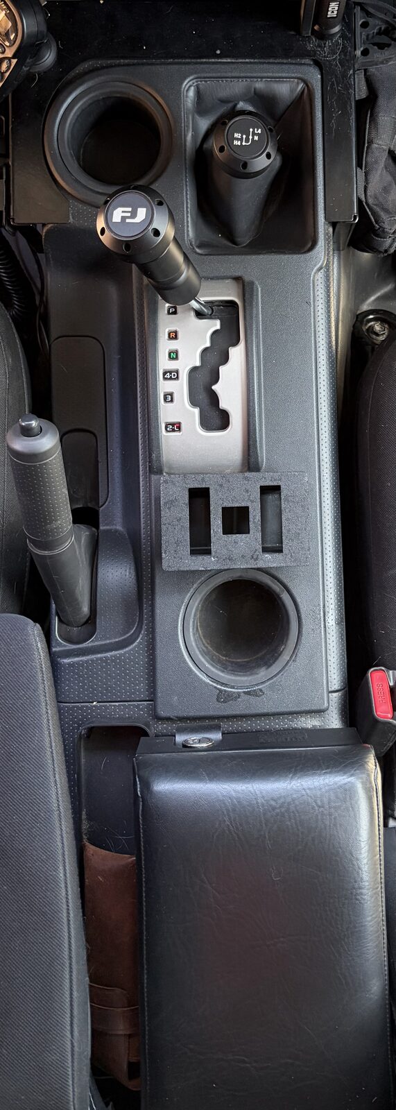
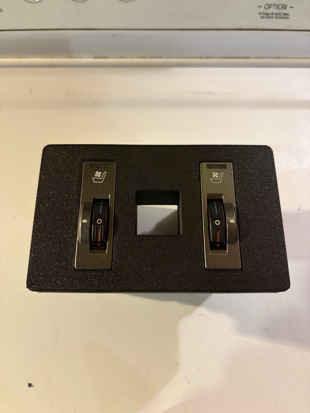
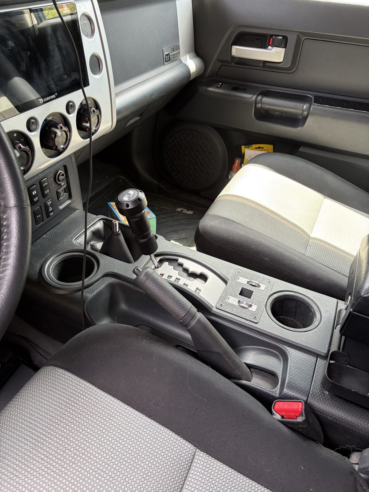
The switches also need somewhere to live. The FJ console has a blank opening next to the cup holder that's the right size for the pair. We printed a bezel that drops into that opening, holds both switches on their factory clips and leaves a slot in the middle for a USB-C port. The first print got the fit right and the layout wrong; the final one is in the free files along with the connector shroud below.
The switch cavity is an 8 by 16 mm opening, 14 mm deep, with twelve pins on a 2 by 6 grid at 2.0 mm pitch and a clip channel for clocking. At that pitch the wall between printed terminal channels works out to about zero, so a printed channel grid is a dead end. What works is a glue-capture shroud: seat the crimped terminals on the switch pins, which sets the spacing for you, slide a hollow printed shell over them, bond the terminal bodies to the shell with epoxy, cure, and pull the whole thing off. Now it's a plug.
- Shroud: 7.7 by 15.7 mm outside, 16 mm tall (12 mm insert plus a 4 mm rear collar), 1 mm walls, clip notch on one long wall, pull tab at the back. The STL is in the free files.
- Terminals: Yazaki 0.64 / 025 unsealed females.
- Adhesive: epoxy. CA is brittle under vibration. Keep it off the contact springs and never bond to the switch pins.
The first shroud packed the terminals tightly enough that neighboring bodies touched. Symptoms: functions in the wrong detent, the blower running in "off," the relay chattering in heat mode. Pull the shroud and everything worked, which told us the pin map was right and the problem was mechanical. The fix is thin-wall heat shrink on every terminal body before it goes into the shroud. Do that before you glue, because glue is one shot.
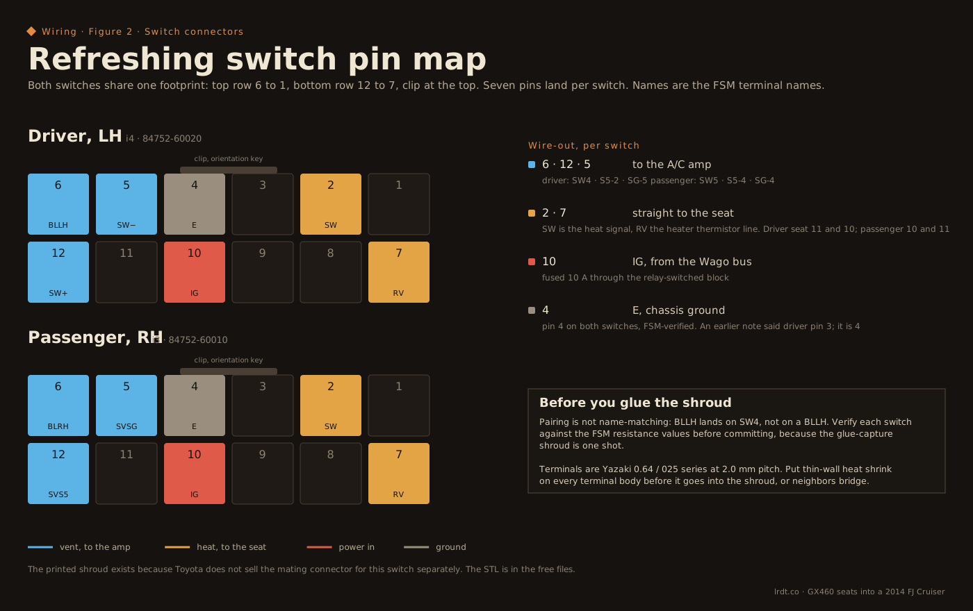
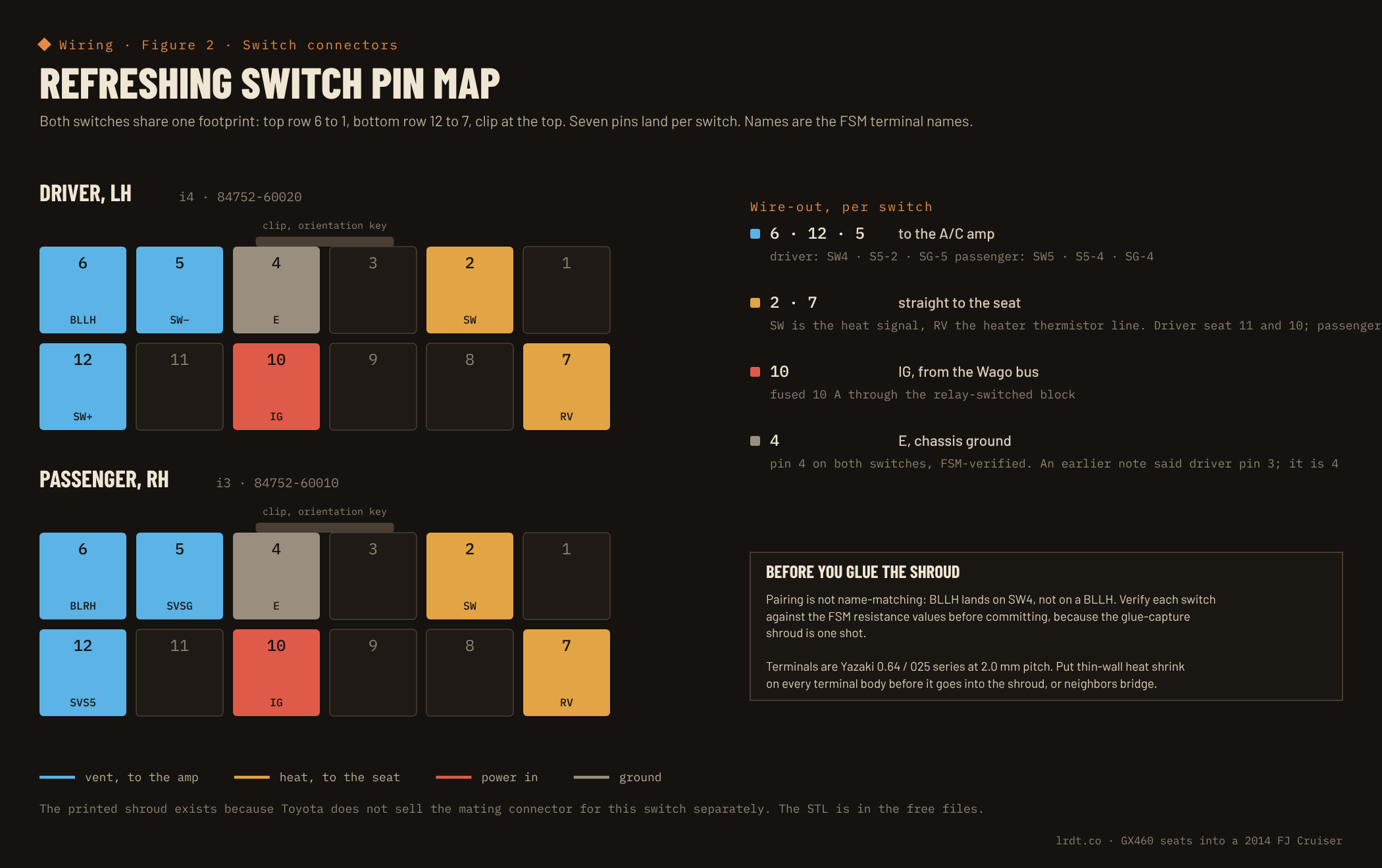
Before anything gets glued, resistance-test the switch across its detents. The FSM values are 1.33 to 2.47 kΩ, 17.9 to 33.2 Ω, 2.17 to 4.03 kΩ and 0.28 to 0.52 kΩ across the pin pairs. That validates the switch and confirms the pin map at the same time. We found a dead passenger switch this way, eventually: it wouldn't drive heat on either seat, the driver switch drove heat on both, so the fault followed the switch. The switch signals by resistance, so probing it for a voltage was misleading; the substitution test was the diagnosis. The replacement 84752-60010 is in the console now and waiting on its wiring.
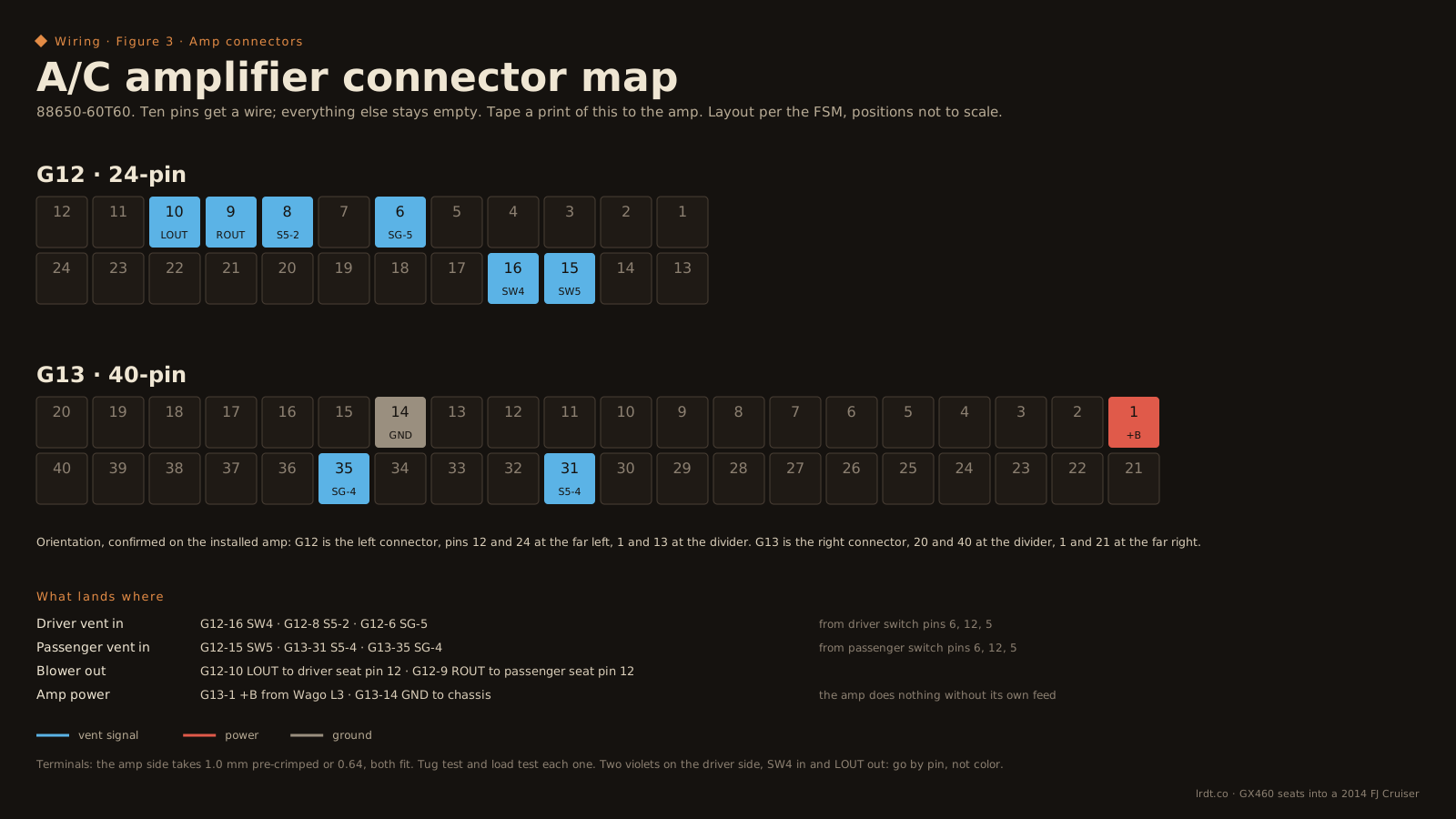
The pairing from switch to amp is not name-matching. BLLH does not land on a BLLH. Wire it exactly as the figures show.
The amplifier
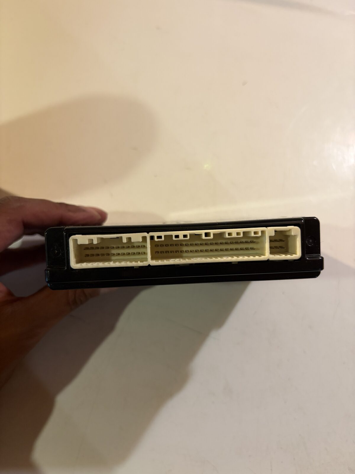
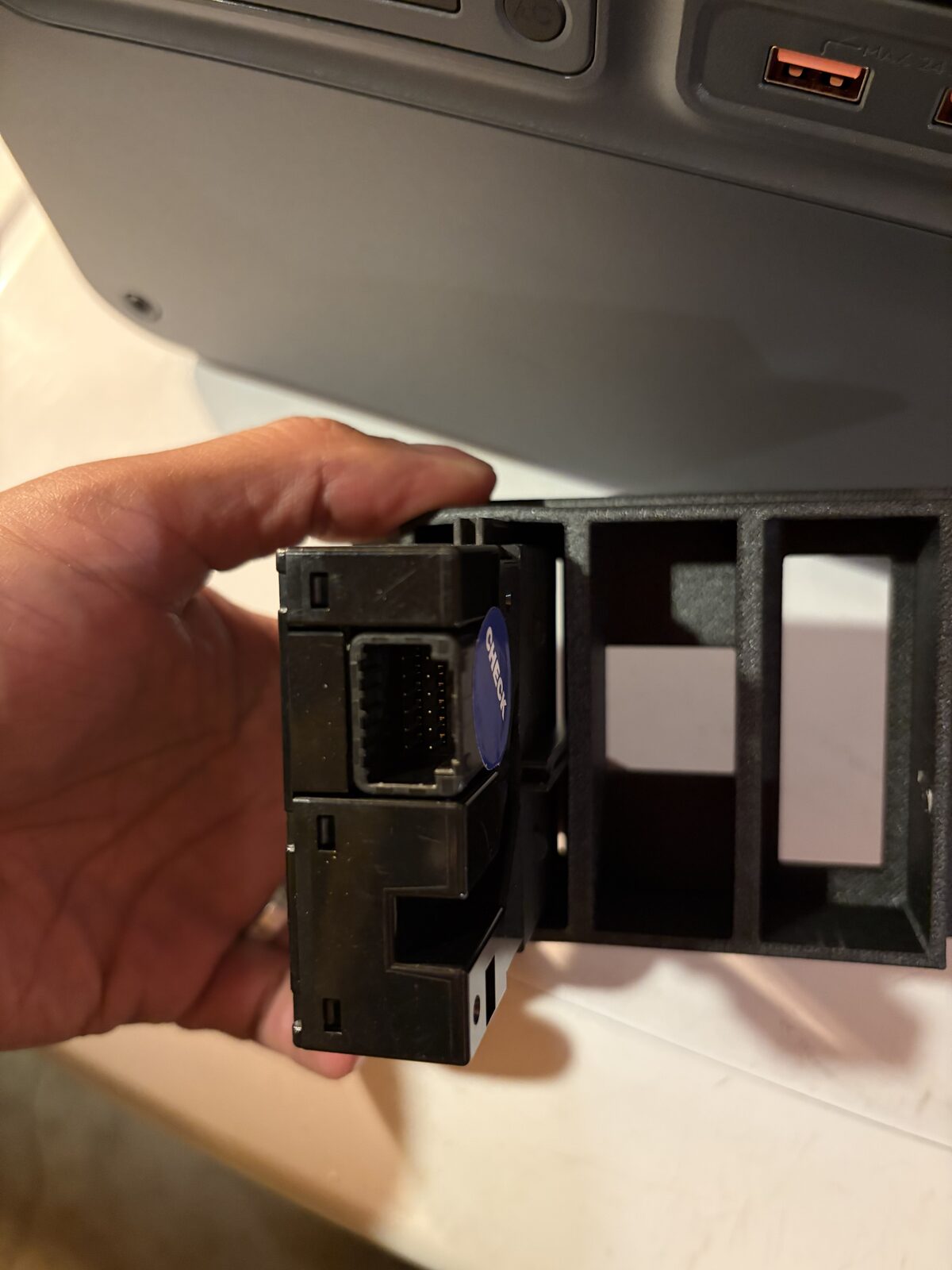
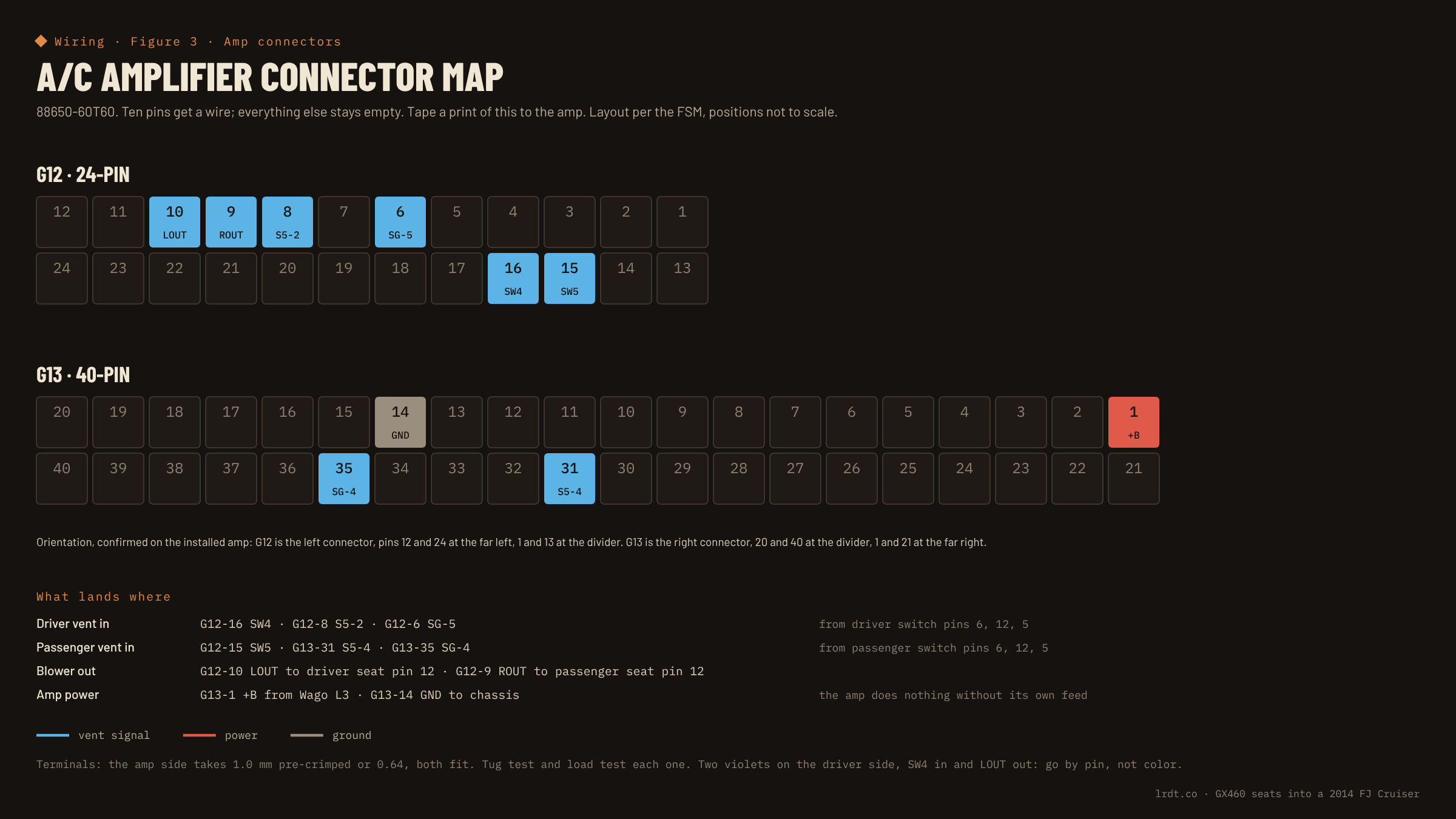
The A/C amplifier is 88650-60T60, mounted low in the center dash. It's an active part: without its own +B on G13-1 and ground on G13-14 it does nothing, however perfect the signal wiring. Its pins are scattered across two segmented connectors, a 24-pin G12 and a 40-pin G13, so a printed shroud doesn't apply. Crimp individual terminals onto the ten pins you need, flag each wire with heat shrink at the amp, and tape a print of Figure 3 to the amp so the map lives with the part.
Two terminal options both fit the amp pins: 1.0 mm JAE, which came pre-crimped on leads, or the same 0.64 Yazaki as the switch. Use the JAE if it grips under a tug test and the leads are a usable length; otherwise hand-crimp the 0.64. Either way, meter under load before you call it done. A loose terminal reads fine static and fails on washboard. Secure the small signal wires with silicone, since there's no factory harness holding them.
The seat side, and the one-pull disconnect
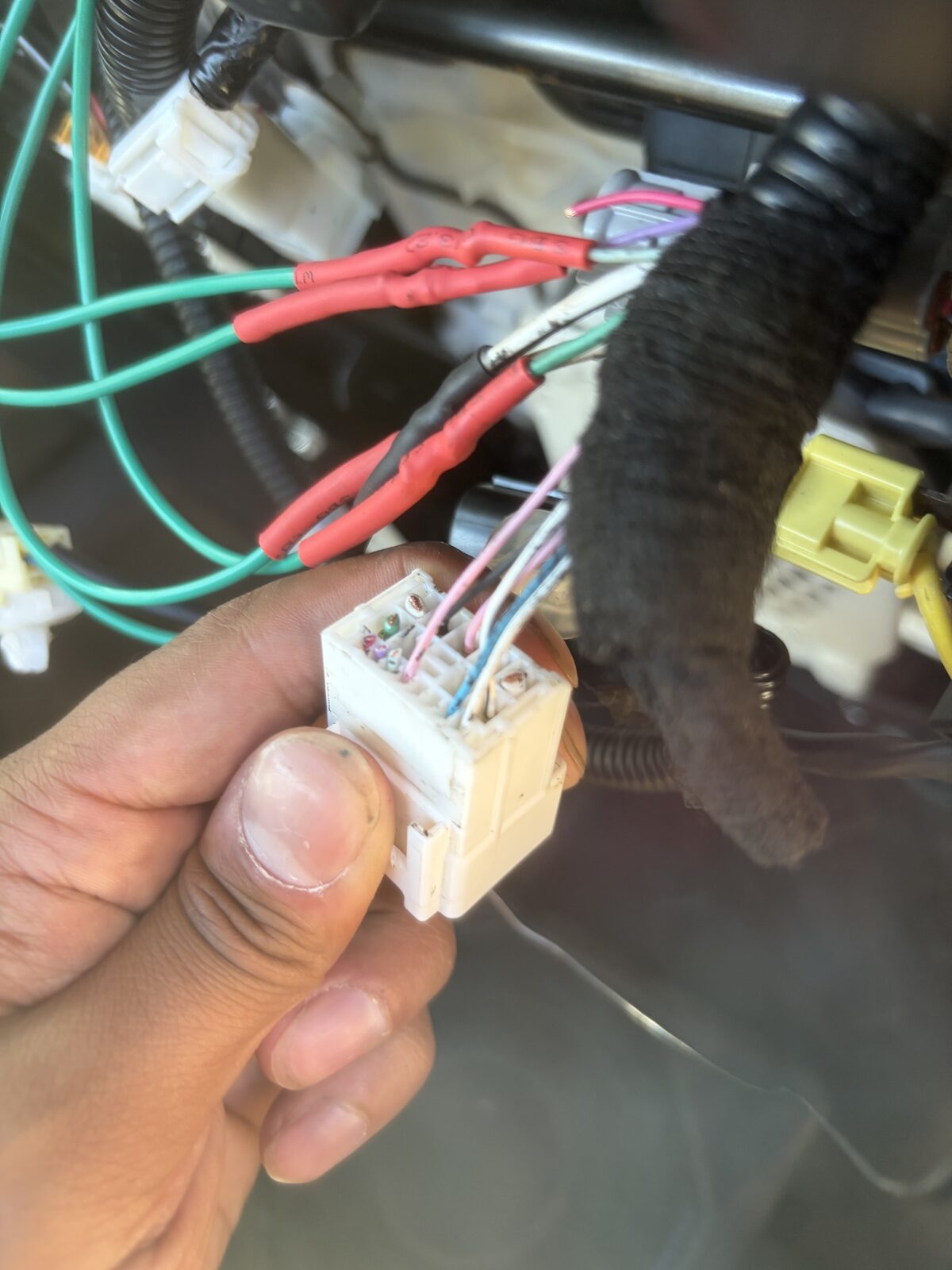
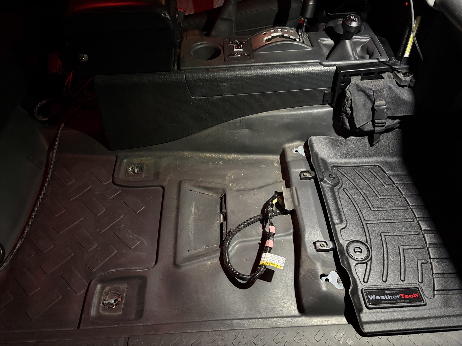
The GX seats stay in the FJ for good, so the Lexus seat plug has no reuse value. De-pin the wires you need from the housing and throw the housing away. Release the secondary lock, back each terminal out the rear with a pick, and label every wire by pin number and function as it comes out, because pins 10 and 11 are swapped between the two seats and you will not remember which is which at the bench.
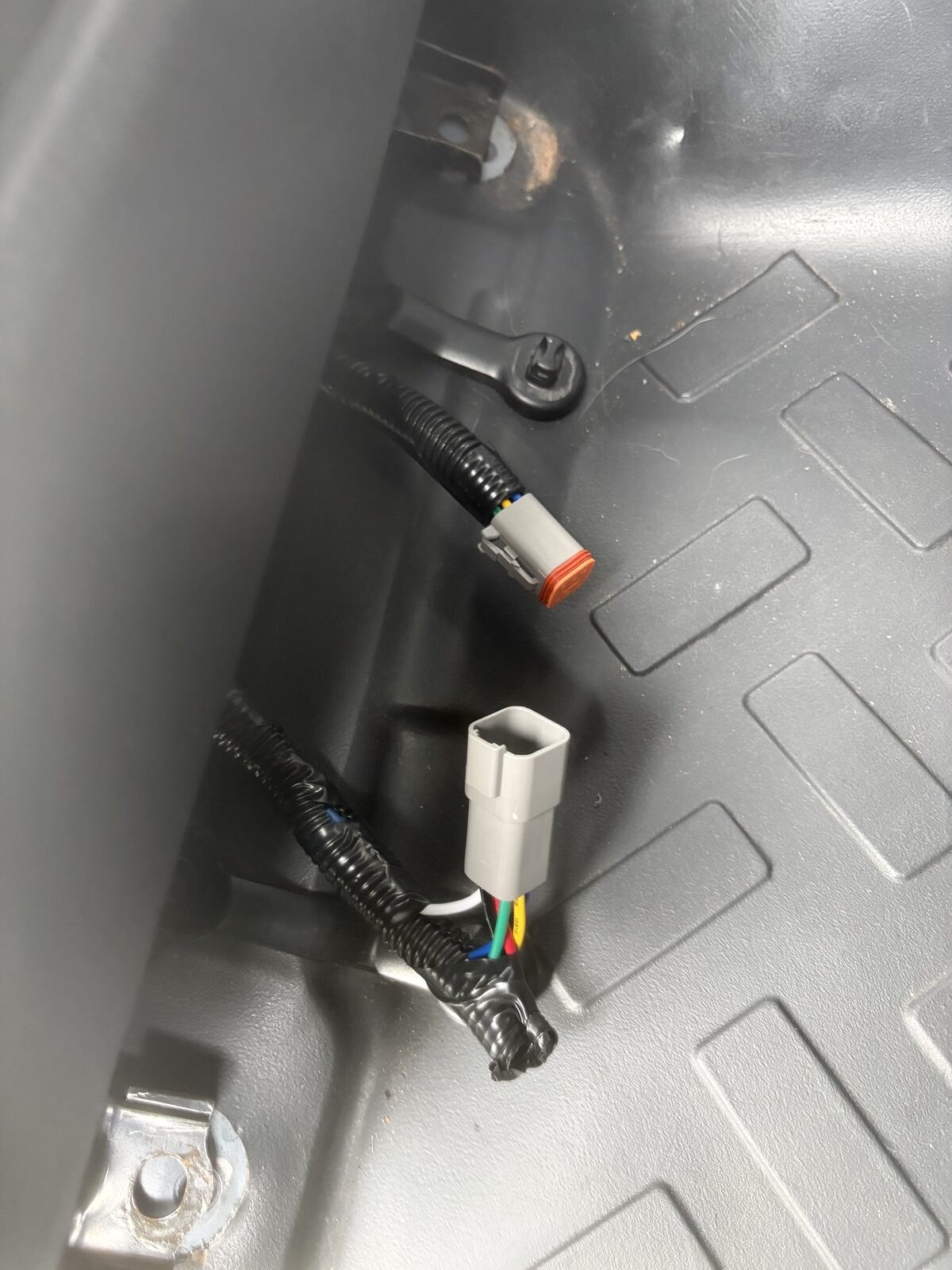
The wires go into one Deutsch DT 6-way per seat, with contacts rated for the 20 A motor circuit, not signal-grade ones. The seat comes out with one pull. On the driver side there are two pink wires at the connector; SYSB is the one in the pin 3 position, picked by position and never by color. Join SYSB and the pin 1 motor wire into one conductor with solder, not a crimped butt splice, so both share the red DT cavity.
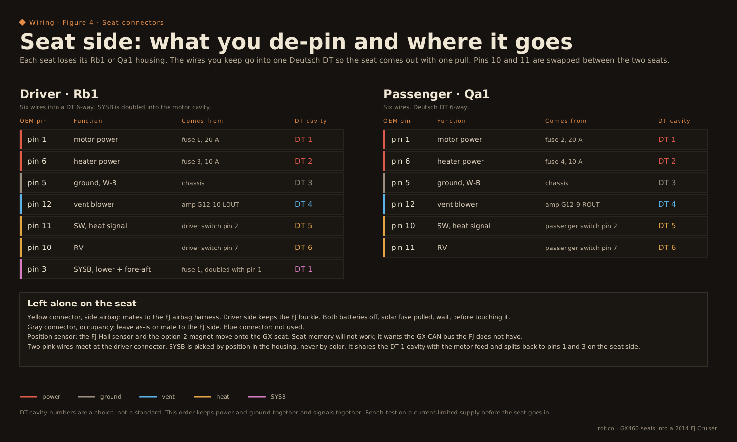
As terminated, both seats
| Deutsch wire | Function | Driver Rb1 | Passenger Qa1 |
|---|---|---|---|
| Red | motor power (driver: plus SYSB, soldered join) | pin 1 + pin 3 | pin 1 |
| White | heater power | pin 6 | pin 6 |
| Black | ground | pin 5 | pin 5 |
| Blue | vent, from the amp | pin 12, LOUT | pin 12, ROUT |
| Yellow | SW, heat signal | pin 11 | pin 10 |
| Green | RV, heater thermistor line | pin 10 | pin 11 |
Same colors mean the same functions on both sides; only the seat cavities differ. The yellow here is a climate signal, not the SRS yellow. Keep them visibly apart near the pretensioner connector. We left the three signal lines unsoldered at the console end until the functional test passed, then soldered.
What you leave alone
- Yellow connector, side airbag. Mates to the FJ airbag harness on both seats. Transfer the FJ seatbelt buckle and pretensioner onto the GX driver seat; the FJ SRS module expects the FJ pretensioner's resistance. Full power-down first: both batteries off, solar fuse pulled, wait.
- Gray connector, occupancy sensor. Leave it, or mate it to the FJ side.
- Blue connector. Not used.
- Position sensor. The Lexus seats don't have the FJ's fore-aft Hall sensor. Transfer the FJ sensor and its magnet in the option-2 orientation, leave the magnet in its shield so the factory gap holds, and bolt the assembly to a rail hole with a nut behind it. The SRS light going out at key-on is the proof.
This is the part we won't walk you through. The side airbag, the pretensioner, the occupancy sensor and the position sensor are all part of the FJ's restraint system, and the only acceptable outcome is that they go back exactly as the FJ expects them. We did ours with both batteries disconnected and the solar fuse pulled, and we left out the steps on purpose. If you aren't already comfortable working on SRS components, pay someone who is. If the SRS light stays on, something isn't right, and that's the end of the install until it's found. Your airbags, your responsibility.
Bench first, then bolt in
- Print the shroud and confirm it slides into the switch cavity, seats to depth, and the clip notch clocks. That's the fit test.
- Crimp the switch terminals (0.64) and the amp terminals per Figures 2 and 3. Heat shrink on every switch terminal body.
- Resistance-test each switch against the FSM values.
- De-pin both seats and build the Deutsch disconnects. Driver gets the SYSB join.
- Bench test on a current-limited supply: motors first (driver lower motors prove SYSB), then heat, then vent through the amp. Swap left and right to make sure heat and vent aren't crossed.
- Glue the shroud, cure, pull the plug.
- Install. Seat bolts are 14 mm at 27 ft·lb. Transfer the airbag harness, buckle, pretensioner and position sensor. Route and secure everything.
- Validate: SRS light on at key-on, then out. Seatbelt warning works. Key off with the solar fuse pulled, the seats go dead.
Bonus: the console top
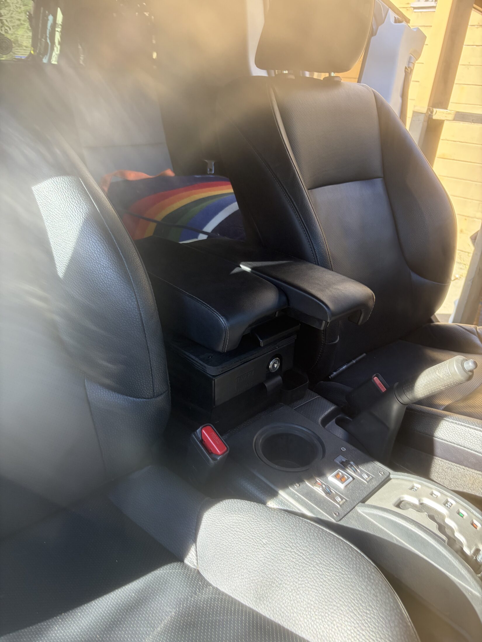
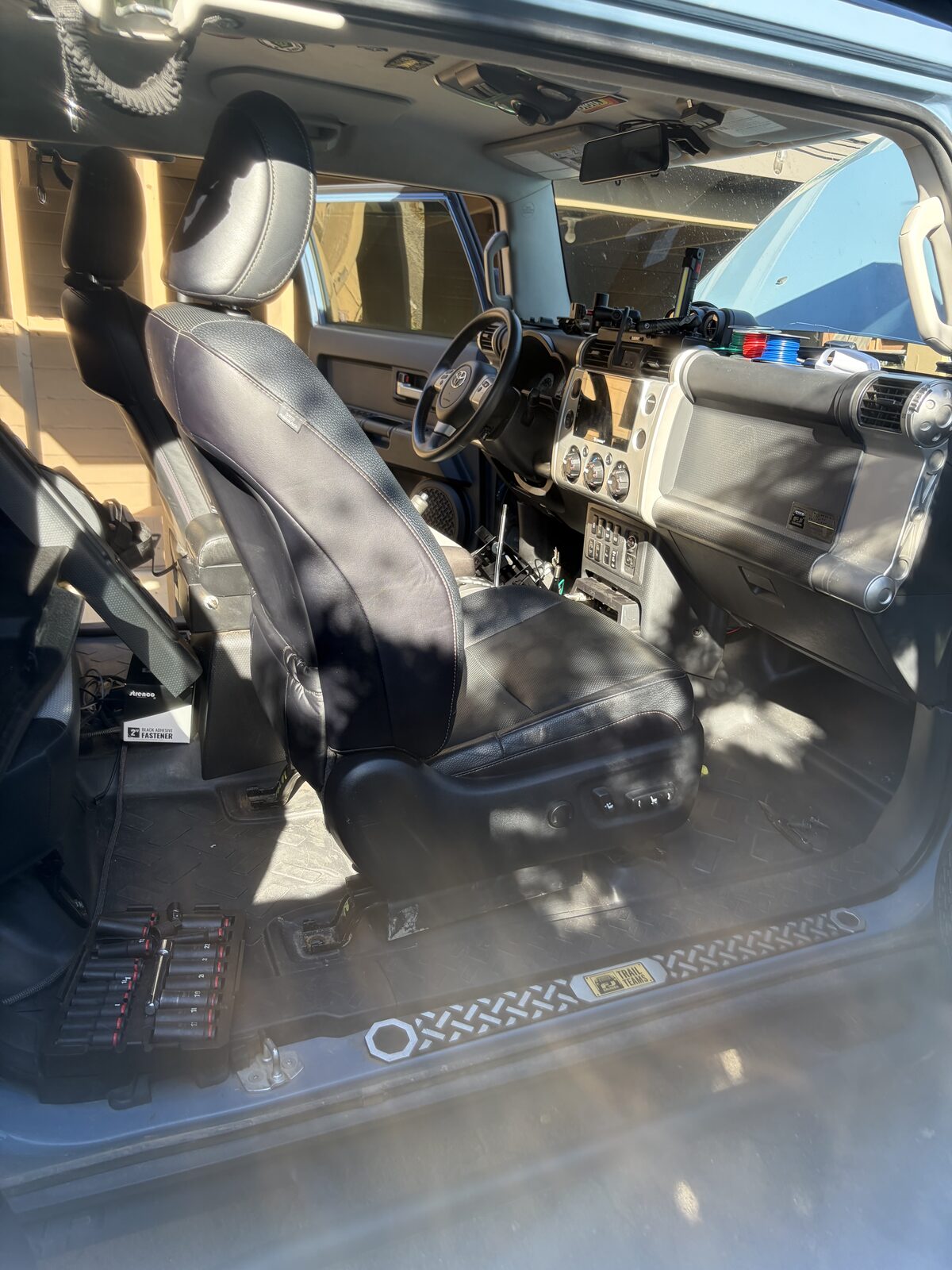
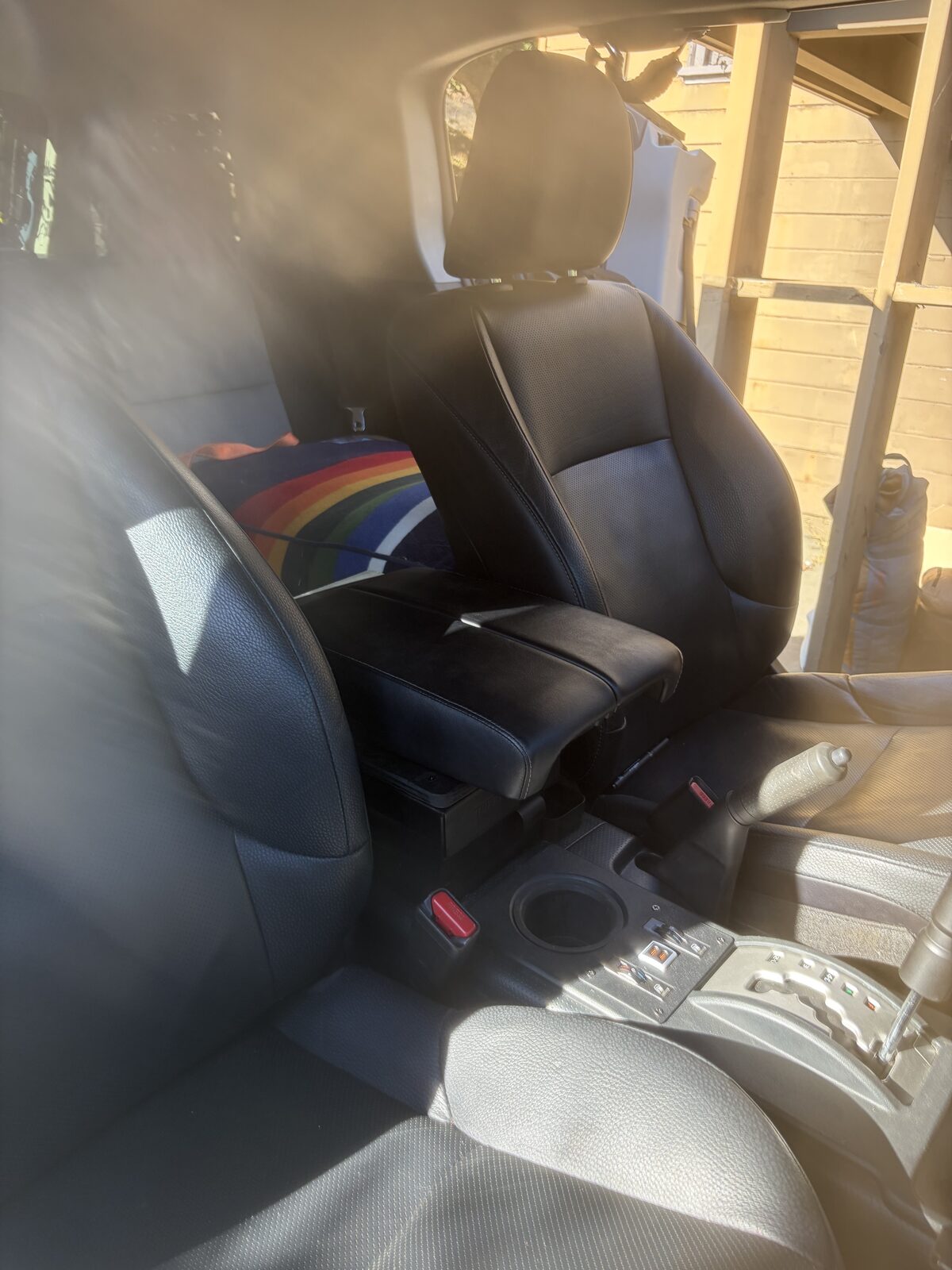
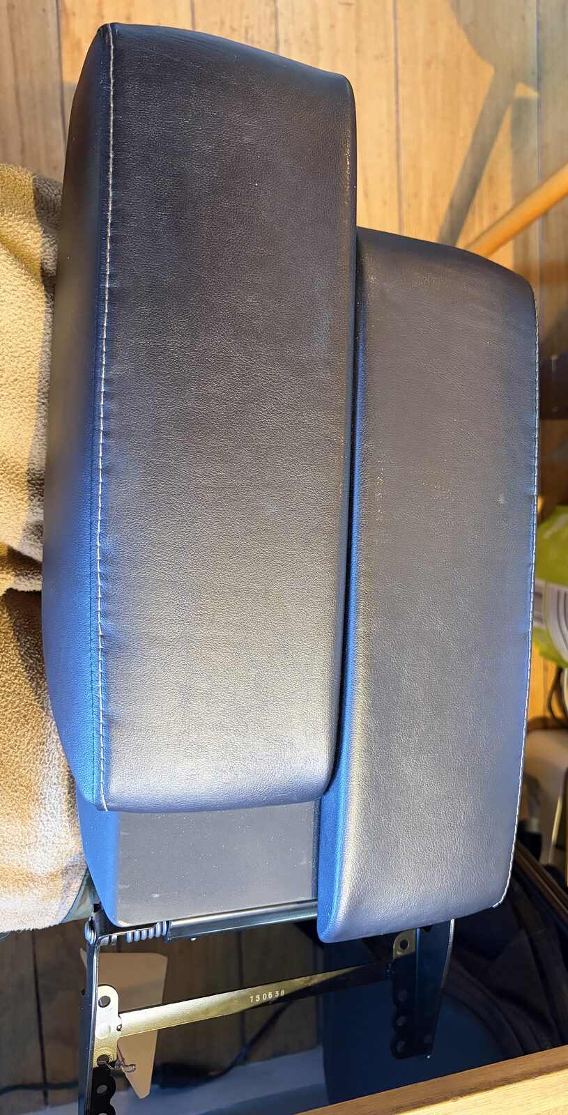
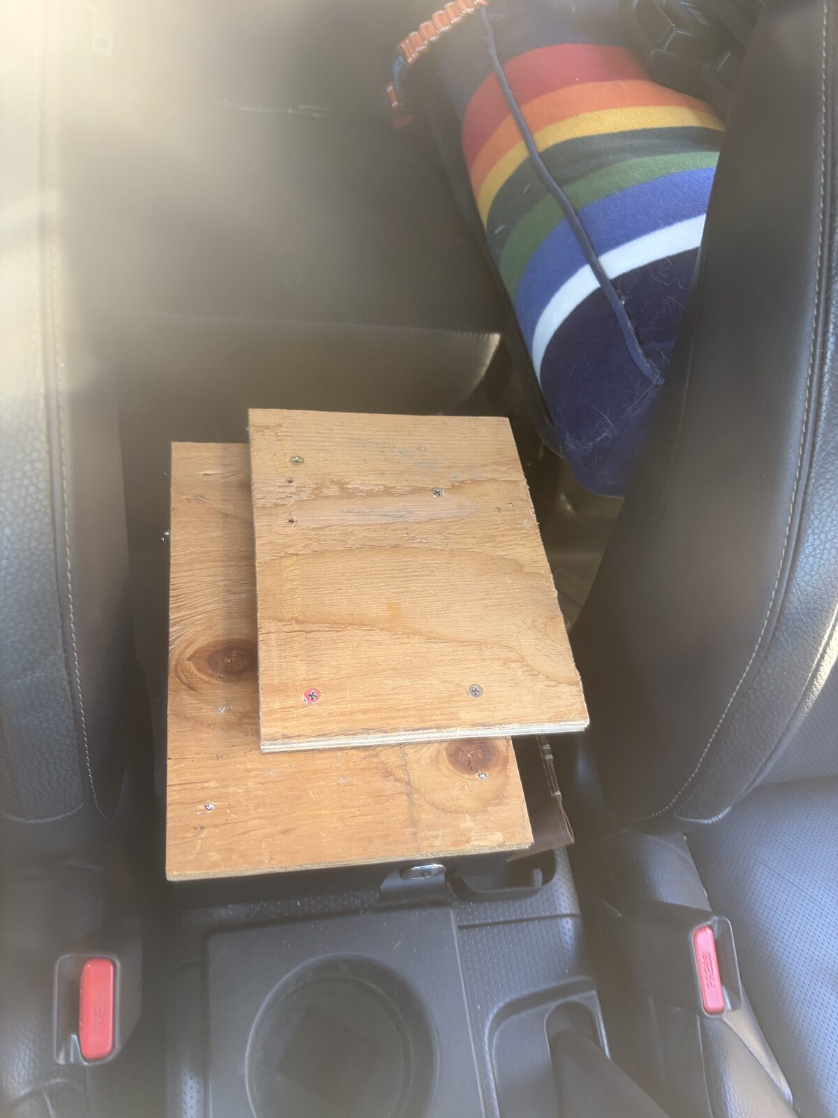
The seats came with the GX center console lid, and it's the better armrest by a mile, so it came along. The FJ side is a Tuffy security console built for the truck. Install the Tuffy, pull its leather top cover off, and you're left with the steel lid and its screw holes. Cut a piece of plywood to the lid, bolt it down through those holes, paint it black, and screw the GX console cover to the plywood. That's the whole mod.
The reason to bother is the sliders. The GX lid is split down the middle and each half rides on its own track, so the driver can pull their side forward and rest on it while the passenger half stays back. With the passenger half back, the rear cup holder is still usable. Nothing on this part of the build deserved an engineering drawing; it's a tape measure, a jigsaw and a can of paint.
Where it stands
Heat works on both seats through the driver switch. The lower motors work with SYSB joined. The relay triggers only with the key on. The bridging problem is solved with heat shrink. Two things are still open as of this writing. The replacement passenger switch is in the console but not wired yet, so heat on that side still runs off the driver switch until it is. And the vent path is wired per the FSM and LowVoltage's tables but hasn't been bench-tested on this truck. We rushed the seats in for a trip and then moved house, so the A/C side has been waiting. When both are done, this paragraph changes.
If you do this swap, the figures above are free to print and the STLs are in the free files. If they save you a weekend, tell the next guy where you got them. And tell him what we told you: this is what we did, not what you should do, and the risk is his.